
Human Motion Monitor
Published:
Summary
The human motion monitoring module detects when its user falls and uses the LTE module to connect to the internet and send for help. The module utilizes Riot Micro’s Bluetooth based LTE chip for the purpose of communicating fall detection alerts. The LTE chip provides the user with freedom to leave the range of a Wi-Fi or Bluetooth network. Riot Micro’s Bluetooth based LTE module allows for much lower power usage compared to normal LTE module. A low power rating is important in this application as it allows for longer battery life. The initial purpose of this project was to provide Riot Micro with a demo application of their RM6100 product through the human motion monitoring module. Over the course of the project the foundation of the fall detection algorithm and NRF52 integration was built in addition to the server side alert system.
Background
The human global population is aging as many states across the world are experiencing an increase in quantity and proportion of older persons in their society. The number of people of age 60 or older is expected to rise from 962 million globally (2017) to 2.1 billion in 2050 and 3.1 billion in 2100.[1] A consequence of this social transformation is that advances in technology are required in order to support the aging population.
One of the leading causes of senior emergency room visits is falling. The motivation for this project was to reduce the severity of those hospital visits due to falling by decreasing the response time, especially for patients who routinely go outside the reach of a Wi-Fi network. There currently exist monitors for fall detection but they rely upon Wi-Fi and Bluetooth networks to communicate alerts. One of the limitations of LTE is that the chips which use it require a lot of power. Riot Micro’s product the RM6100 solves this problem as it is marketed as a lightweight LTE solution geared toward IOT applications. The RM6100 uses much less power than normal LTE chips.
Sponsor
Riot Micro(acquired by STMicroelectronics) develops industry-leading wireless chipsets for smart objects in the Internet of Things. Their breakthrough IoT platform-on-a-chip simplifies cellular connectivity for current-generation applications such as smart metering and vehicle telematics, as well as a new generation of smart objects that range from wearables and smoke detectors to parking meters and traffic lights.
Design
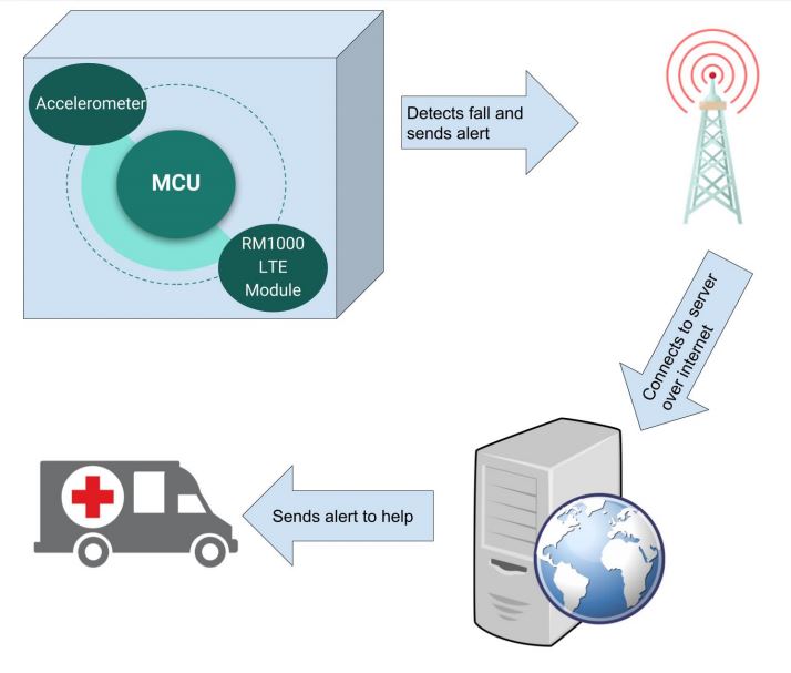
At a high level of abstraction our team is responsible for two major components of the project’s design. The first component is a conglomeration of hardware that facilitates turning the detection of a fall into an alert that can be sent over an LTE network. The second major element deals with the handling of this alert message. It comprises a server that receives messages from the device and then sends email and SMS alerts to someone that can help the fallen person. In order to gain a clear understanding of how these parts interact please refer to the system level diagram shown in the system level diagram. The following subsections will discuss the design of these components in detail
The reliability of this device is dependent on how well it can detect falls and discard false positives. Thus, it was critical to the success of our project to implement a proper fall detection algorithm. This section will discuss some of the theory behind detecting falls.
For this project, we followed an Analog Dialogue article by Ning Jia and a paper by Wu, F., Zhao, H., Zhao, Y., and Zhong, H. These resources provide guidelines on the settings to use for the accelerometer and they formalize the necessary math and physics for detecting falls.
Below is the project’s system level diagram. This diagram shows how the major components of our project interact. The human motion monitoring system containing an accelerometer, a micro-controller, and an LTE module detects when its user falls. In the event that the module detects a fall, it will use the RM6100 LTE Module to send an alert to a server. The picture of a telecommunication server was added to show that the module connects to the internet over a form of LTE protocol implemented by telecommunication towers. Once the server receives the alert it forwards that alert in the form of an email to the user’s designated help address. The human motion monitoring system containing an accelerometer, a micro-controller, and an LTE module detects when its user falls. In the event that the module detects a fall, it will use the RM6100 LTE Module to send an alert to a server. The picture of a telecommunication server was added to show that the module connects to the internet over a form of LTE protocol implemented by telecommunication towers. Once the server receives the alert it forwards that alert in the form of an email to the user’s designated help address.
The accelerometer used for this project, the ADXL345, measures acceleration in three directions, x, y and z. Usually, when the accelerometer is stationary, the only force acting on it is gravity. When this is the case the vector sum of the accelerations in each direction must be equal to 1g. The vector sum of the accelerations is defined as
During a fall, there are two easily distinguishable states - free-fall and impact. By tracking the magnitude of a we can determine when the accelerometer attached to a falling person experiences one of these scenarios. Below is a picture taken from the Analog Dialogue article by Ning Jia and It depicts how each directional acceleration behaves during a fall.
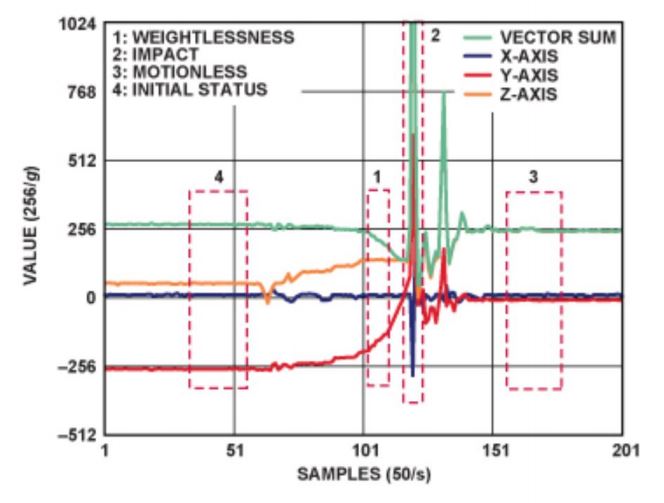
As shown in the figure, during a free-fall the accelerometer experiences weightlessness as the vector sum tends towards 0g. Next, upon impact the vector sum spikes and reaches values upwards of 3g. So, we can design an algorithm that checks for certain thresholds to be breached, indicating a free-fall followed by an impact. In addition, the reliability of this method can be improved by also measuring the orientation of the accelerometer before and after the fall. This can be implemented by storing the values of the acceleration vectors preceding a fall and comparing them to the acceleration vectors after the fall. If they are sufficiently different, it is likely that the person who has fallen is no longer standing upright.
Microcontroller and LTE Module Selection
The following is a brief discussion of the microcontroller used for this project and the RM6100 LTE Module. Choosing a microcontroller and LTE module for this project was not part of the project, since both these components were specified by the project sponsor. The LTE module used is the RM6100 because one of the primary goals of the project is to demo Riot Micro’s technology. Additionally, engineers at Riot Micro found that the Nordic NRF52832 microcontroller is suitable for interfacing the RM6100 thus this is the device used in this project and other design choices were based on this selection. To speed up development, the NRF52 Development Kit is used.
Fall Detection
An accelerometer that reliably measures the types of accelerations seen in a fall and is compatible with the rest of the hardware is absolutely crucial to the design. The ADXL345 is widely used in numerous applications, including other instances of fall detecting devices. In fact, the resources mentioned in the Fall Detection section of Theory (Analog Dialogue article, Fall Detection paper) specifically use this accelerometer.
The ADXL345 offers 13-bit resolution and a range of ±16g. This data is outputted as 16-bits of twos complement data and is read using either a 3 or 4-wire SPI (Serial Peripheral Interface), or an I2C (Inter-Integrated Circuit) interface.
The original design specified a 4-wire SPI interface as opposed to I2C as it offers much higher speeds and does not require pull-up resistors on the data lines. Human movements actually occur at low frequencies (100Hz is typical) meaning the speeds offered by SPI are not necessary for this application. The major design pivot to I2C is was done because more commonly implemented and easier to use.
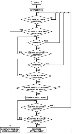
Once a secure I2C connection is established, acceleration data for each direction is streamed into the microcontroller, where the vector sum calculation from the Theory section is performed. Next, the fall detection algorithm flow chart from an application note shown in the below diagram is followed. Note that in the design, interrupts are not utilized as it is easier to test by manually setting thresholds for free-fall and activity (impact) and checking constantly to see if these thresholds are breached. The actual sum that is compared to the thresholds is an average of the last 25 sums so that outliers are removed. In addition, there is a timer on the free-fall state so that if a free-fall is not immediately followed by an impact, it is ignored and the free-fall state is reset.
RM6100 Communication
After the microprocessor decides that a fall occurred it must notify the RM6100 LTE module so that it can ping the server. The RM6100 is controlled using AT commands that are sent over a UART (Universal Asynchronous Receiver/Transmitter) interface. Implementing the UART connection involves connecting the RX/TX pins of the RM6100 and the Nordic MCU. Nordic provides a UART driver sending the commands over UART. Appendix B contains the code used for creating a UART connection. Details regarding the RM6100 hardware and its AT command set have been omitted due to copyright issues.
Testing
Testing Fall Detection
To quantify the reliability of the fall detection algorithm a series of tests were performed. First, four scenarios were identified. Two of the scenarios, backwards and forwards falls, were expected to trigger the sending of an alert. The other two scenarios, brisk walking and sitting, are possible false positives.
The test setup involved attaching the development board with the accelerometer to a person and having them recreate different falls. The development board was connected to a computer with a long cable and was programmed to issue the alert “Send Help” if a fall was detected. The threshold parameters for free-fall and impact were set as follows:
| Parameter | Value |
|---|---|
| Free-Fall Threshold | 0.58g |
| Impact Threshold | 1.96g |
An alert should be sent if there is an acceleration vector sum measured above the impact threshold immediately following a free-fall. During testing, some types of falls (ie. slow, staggering falls) a free-fall never triggered but the impact would be very large. The impact of these types of falls were much greater than 1.96g, in fact they were often upwards of 3g. To capture these edge cases, an additional impact threshold was programmed to trigger for any impact larger than 2.7g. The accelerometer was sampled at 400KHz.
Of course, with this set up there are many sources of variability and cases that may not be realistic. These include:
No fall is the same. It is impossible to consistently recreate a perfectly real fall. Despite this, the falls that were conducted were still real enough to be harmful to an elderly person so should still trigger an alert and are thus still valuable tests.
When falling intentionally, it is a reflex to try to lessen the severity of the fall, so the impact magnitudes and lengths of free-falls are perhaps less than they would be during a real fall.
It depends where on the body the accelerometer is. For the most part this was controlled, some of the tests were run with the accelerometer fixed near the sternum, where a pendant might hang. For others it was fixed to the hip. It was observed that at sternum height there was a lower impact recorded but a more pronounced free-fall. At hip height, the free-fall threshold was often not breached but the impact was much larger, and would trigger an alert. This showed that our setup was robust and was reliable regardless of the placement.
Fall Testing Results
The below table shows the results for each scenario. Note that a passed test for forward and backward falls means that a “Send Help” alert was sent, and a passed test for walking and sitting means that an alert was not sent.
| Fall Senario | Percentage Passed |
|---|---|
| Forward Falls | 87 |
| Backward Falls | 87 |
| Sitting | 80 |
| Walking | 80 |
The sensitivity and specificity of these results on their own are likely inadequate for an actual medical device. However, these results are acceptable considering:
The tests were strictly based on an acceleration threshold algorithm. With the inclusion of an algorithm that calculates the orientation of the accelerometer before and after the fall, the specificity should increase massively. This would also allow for stricter thresholds so sensitivity would also increase.
A limited number of tests were conducted. With more time for testing, more scenarios could be explored and it is likely that the sensitivity and specificity would increase.
In a realistic setting, specificity is less important than sensitivity. On a final product of this nature a mechanism could be provided for the user that allows them to manually cancel the alert if a fall did not actually occur. Therefore, the device could be calibrated to be over sensitive and still perform desirably.
Fall Testing Data
This section shows plots for the acceleration vector sums that were captured during fall testing. The plots do not contain data from all tests. Instead, they contain exemplary tests that make it clear to see why they passed or failed. By examining the failed cases, recommendations on how to improve the fall detection algorithm can be made.
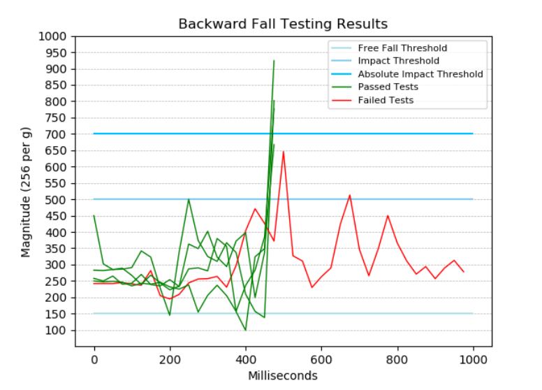
This plot shows how the vector sum of the accelerations change with time, during a backward fall. The free-fall threshold line at 150(0.58g) marks the values of this vector sum for which a free-fall event will be triggered. The impact threshold at 500 ( 2g) describes the acceleration which, if experienced immediately after a free-fall, will trigger an alert. The absolute impact threshold at 700(2.7g) is in place to trigger alerts for any impact above this amount. Green lines indicated passed tests, which in this case means an alert was sent.
Backwards falling took the form of a straight down collapse in which the person ended up on their back, or a backwards stagger and then a collapse. The failed cases for this scenario were for backwards staggering type falls. As shown by the red line in the plot, free-fall is never experienced since they are somewhat supporting themselves as they fall. In most cases, the drawn out staggering would be ended by a large impact (enough to trigger the absolute impact threshold). However, the failed cases result from a long fall with a somewhat softer landing. These types of falls could be distinguished by looking for sustained large impacts (the three large peaks of the red line) that indicate abnormally heavy staggering.
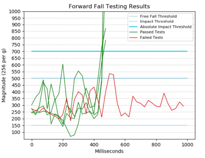
This plot shows how the vector sum of the accelerations change with time, during a forward fall. The free-fall threshold line at 150(0.58g) marks the values of this vector sum for which a free-fall event will be triggered. The impact threshold at 500 ( 2g) describes the acceleration which, if experienced immediately after a free-fall, will trigger an alert. The absolute impact threshold at 700(2.7g) is in place to trigger alerts for any impact above this amount. Green lines indicated passed tests, which in this case means an alert was sent.
Forward falls were recreated similar to backwards falls: quick forward collapses or forward staggering slips. Similar to backward falls, the algorithm fails to detect very drawn out staggering falls since free-fall is not experienced and the final impact is relatively low.
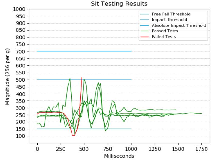
This plot shows how the vector sum of the accelerations change with time, while sitting down. The free-fall threshold line at 150(0.58g) marks the values of this vector sum for which a free-fall event will be triggered. The impact threshold at 500 ( 2g) describes the acceleration which, if experienced immediately after a free-fall, will trigger an alert. The absolute impact threshold at 700(2.7g) is in place to trigger alerts for any impact above this amount. Green lines indicated passed tests, which in this case means an alert was not sent.
Sit tests involved a mixture of very slow sitting and a more violent falling into a chair. For relatively normal sitting, free-fall is never achieved since the person is lowering themselves rather than being dropped. For very fast sits however, a very pronounced free-fall state can be entered, and although the impact is relatively small it is enough to trigger an alert in some cases. Looking at the data in the sitting results plot, it is clear that the solution to reducing false positives would be to increase the impact threshold slightly.

This plot shows how the vector sum of the accelerations change with time, while walking. The free-fall threshold line at 150(0.58g) marks the values of this vector sum for which a free-fall event will be triggered. The impact threshold at 500 ( 2g) describes the acceleration which, if experienced immediately after a free-fall, will trigger an alert. The absolute impact threshold at 700(2.7g) is in place to trigger alerts for any impact above this amount. Green lines indicated passed tests, which in this case means an alert was not sent. Walking tests consisted of normal walking as well as some very brisk walking with sharp direction changes. The failures occurred when directions were changed quickly at the same time as stomping, causing a small free-fall then impact.
Server-side Architevture
dweet.io is a simple publishing and subscribing service for IOT devices. It enables states and data to become easily accessible through a web based RESTful API.
Digital Ocean is a cloud services platform, which allows for simple setup of servers. A Digital Ocean droplet is a rented server that can run Linux based applications. In the context of this project, Digital Ocean is equivalent to AWS or a Raspberry Pi connected to the internet.
Architecture Diagram
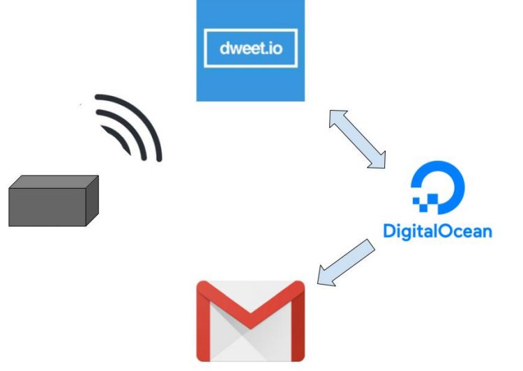
The alert sent by the module changes a state stored by dweet.io. The Digital Ocean droplet listens for a change in the state accessible by the module. When it detects a change in the state it then sends an email to the user’s designated help address. After sending the email, the Digital Ocean droplet changes the dweet.io state back to normal.
Accessing dweet.io State
The LTE module is able to access the state stored by dweet.io using a web-based URL API. This means the state is connected to a specific URL determined by dweet.io’s API. The following is an example of accessing the state for writing:
https://dweet.io:443/dweet/for/6c749fd2-85c3-4315-bbc0-a463c623fa01
The Digital Ocean droplet accesses the dweet.io state using a Python script. An open source package named dweepy provided a Python API for accessing the state on dweet.io’s servers. The package is used for polling for a change in the state connected to fall detection, and for changing the state back to normal once an email is sent.
Sending Email
An email is sent to the user’s designated help email by running the Python script from section B.5 on the Digital Ocean droplet. This script is triggered when a state change is detected. The steps of the script are:
- Access the Human Motion Monitoring email account
- Setup a secure connection over SMTP
- Send an email to the user’s designated help email address