
Capstone: Drone Relay Station
Published:
My partner Tristan Ford and I worked on this capstone project together. Along the way we learned about communication protocl, radio hardware, and drone movement/simulation.
Project Background
Aeriosense provides industry leading Unmanned Aerial Systems (UAS) based inspection tools for elevated infrastructures and other difficult to access facilities. Aeriosense is currently developing drone automation software for inspection of elevated infrastructures. Sometimes when inspecting by drone, the terrain can impede the direct path of communication to the UAV. In this case, the pilot can receive a deteriorated video feed, and delayed or no info from the UAV. To resolve this issue a compact and lightweight relay station is to be built and tested that can be placed in elevated locations, midway between the UAV and the operator, or on a UAV itself.
The module should extend the range that drones can transmit information. Additionally, the signal should be more robust over terrain that would otherwise block the signal.
This system will be used by Aeriosense in the implementation of automated UAV drones for assisting the maintenance of power stations in the Rocky Mountains and other rural locations in BC. The drones should be able to fly over the terrain then check for damage on the transmission towers.

Approach Description
At the inception of our project, we had to make a decision as to the brand of drones we would be working with. There were essentially two options in this respect, DJI or Ardupilot drone systems.
DJI Approach
Theory
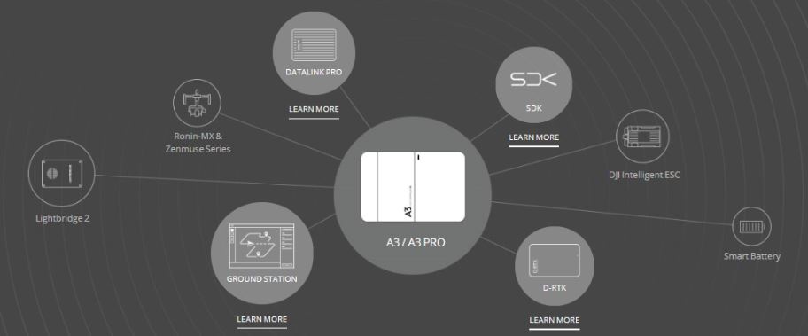
The plan was crutched on the DJI onboard and mobile SDKs. The modern flight controllers and drones released by DJI are equipped with the capability to implement custom flight control via an onboard embedded system. Using several off-the-shelf products from DJI we could, in theory, create a wireless link from a ground station to an intermediary drone and finally to a second final drone.
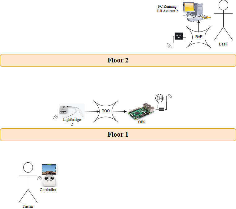
Below is a schematic for our initial design of the system. Wherein, DAD refers to the ground station. BOO refers to the relay station/intermediary drone. And BAE refers to the secondary and final drone. The various floors are imitating obstructions to the signals between components. We would initially test the communication without obstructions, and after feeling confident in the system we could move to different floors.
Equipment and Uses
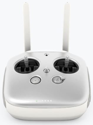
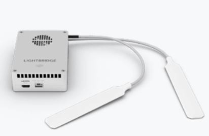
Appendix A - Lightbridge 2 Ground System: As a starting point we would use a real-time controller to send messages through the relay station to the final drone. The controller being held by Tristan is this real-time controller. After a proof of concept, showing that we can indeed send commands through the relay station to the final drone we would adapt the solution to a computer ground station. This would have predetermined commands making the system “autonomous” up to an initial starting command.
Appendix B - Lightbridge 2 Air System: This DJI product accompanies the controller. It receives the messages sent by the controller and inputs them into the drone. This was an attractive idea as it removed the need for us to worry about error checking and other complications related to radio communication. These are industry products having protocols that force stable communication of information.
BOO: The relay station drone. Either a DJI Phantom 4 equipped with the A3/N3 flight controllers or a newer DJI Matrice 600 model. This is required because these are the DJI products that support the onboard SDK. This would allow us to implement custom message routing so that commands from the controller could be relayed to the OES.
OES (onboard embedded system): The onboard embedded system is a microcontroller tasked with receiving the commands from BOO and sending them to BAE. This and the message routing with BOO were predicted to be the most difficult problems to solve. Our initial choice for the microcontroller was the STM32F401re model from Nucleo because on their Developer Website there are examples using the STM microcontroller. We planned on building off of these designs for the Onboards SDK to use in the relay station.
Ground Station Wireless Data Link: These are the sister antennas on the OES and BAE. They are an off-the-shelf DJI product that can send commands from a computer to a DJI drone. This has the same benefits as the Lightbridge 2 in that it removes the necessity of developing a custom radio communication protocol.
BAE: The final drone in the chain. This would be any DJI drone interfaceable with the GSWDL. Both the DJI Phantom 4 and the DJI Matrice 600 can be used for the design of BAE.
PC: The PC connected to the final drone is used to run a simulation software such that we could monitor the actions of BAE without having it fly around in real space. The DJI Assistant 2 is a simulation software provided by DJI.
Methods and Testing
Before we purchased any items we conducted a feasibility analysis of our design. This was governed by several factors.
- Does Aeriosense have the necessary components on hand.
- If not how expensive are they.
- If not can we rethink the design to accomodate what is available.
- If so are the components useable by us on a daily basis.
- What can we realistically expect from each of these components.
- What documentation exists for the parts we want to use.
- Are there any projects similar to ours that we can reference which used these parts.
- How reproducible/robust will the final product be.
These questions were how we weighed what we would eventually purchase for our project. We attempted to elicit help from DJI’s support team, but unfortunately they were quite unresponsive. We looked further into the SDK and were able to imitate various examples for connecting a drone to the simulator software, however there were no references for a custom project like the relay station. Furthermore, the components we wanted to work with were all quite expensive and not currently possessed by Aeriosense.
In conclusion, after two weeks of consideration, we realized that our solution using the DJI systems we would be creating something that was not reproducible nor robust. We would have to piece together various parts from SDK examples and components that were not made for the purposes we wanted to use them for. Our sponsors agreed, and we decided to pivot in our design.
This initial path we took had several overall benefits to our project development. Although it was not a fruitful endeavor, we managed to create a solid design that we could build from. By brainstorming ideas that could work within the constraints of the DJI systems, we managed to produce some creative ways to solve the communication problem.
The main takeaway being our idea to create a totally separate library of commands that we can send via the radio link. This is our custom API that we will discuss later. By doing this we removed the intricacies of customizing the firmware for a flight controller. This would probably take months of time to figure out in itself.
Secondly, we decided upon our onboard embedded system, the Raspberry Pi, which is still an integral part of the current design. Essentially, this pivot allowed us to keep our original ideas and provide us with an opportunity to work with a different drone infrastructure that suits custom projects.
Ardupilot
The Ardupilot drones are much more custom project friendly. They have a lot more documentation and previous projects that we could reference online. A group of students who previously worked on a project for Aeriosense had been developing with these drones and so they had many parts that we could use exclusively.
Theory
Similarly to our DJI design, below is our overall schematic for how the final product should function. The blocks of the design are equivalent in their function to the ones in the previous schematic. There are a few nuances, however, that are worth noting. For instance, the radio antennas are directly connected to the Raspberry Pi and not the drone. This and the design as a whole will be discussed further.
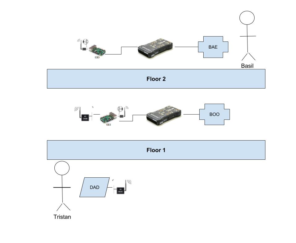
The pillar upon which our project rests is the 3DR Radio Telemetry set. These are the radio antennas that link all the components wirelessly. The reason they are so important is because they possess a communication protocol that provides error checking, frequency hopping and other communication tools to make our lives easier. Basically, we can tell the radio to send a string and not worry about how the string is broken down and reassembled at the other end. All we will see is the string. These radios connect to serial ports on the ground station computer and the Raspberry Pis.
With this tool in our back pocket, we designed an API which on a high level enables commands dictated by the ground station to be sent over the telemetry set. Our API contains a library of commands for the sender side which when chosen, sends a set of serial information to the receiving side. From that serial information, the API on the receiving side is able to interpret the desired command from the ground station from the serial information. Furthermore, we can specify a destination for the message. For example we may want to send a message to BAE from DAD or to BOO from DAD, so naturally this is necessary.
Paired with the API, we are using the Dronekit python package for sending commands to the drones. This is open source software that provides many useful tools. It is also specifically designed to work with Ardupilot drones. The main feature that peaked our interested was the simulated-in-the-loop drone that could be created with Dronekit. This simulated drone connects to a virtual port and acts as if there were a real drone connected to that same port. This allowed us to easily test our scripts for functionality.
Lastly, we require the computers onboard BAE and BOO in order to run the Dronekit software and route messages after being received from DAD. We can also create simulated drones on the Raspberry Pis with Dronekit allowing for testing without a physical drone or worrying about interfacing flight controllers as sometimes custom wiring is required.
With all these pieces in the design forms into the following:
- Desired command is input by the operator on the command line.
- Dad sends this command over the telemetry.
- BOO receives the command.
- If the destination is BOO, translate the message into the corresponding dronekit script and deliver to the relay drone.
- If the destination is BAE, relay the message over the second telemetry to BAE and perform the same as 2a.

Equipment and Uses
DAD: A computer that serves as our ground station. All commands are sent from here.
3DR Radio Telemetry: The radio antennas that connect DAD, BOO and BAE. these provide the wireless communication capabilities.
BOO: A Raspberry Pi that controls the relay station drone as well as routes messages from DAD to BAE. Not to be confused with the relay station drone, BOO references the microcomputer. The drone itself is considered tertiary to our project.
BAE: A Raspberry Pi that controls the second drone. The same as BOO, however it does not have the responsibility of routing messages.
PIXHAWK: The flight controller for our drones. One is connected to each BOO and BAE and in concert with Dronekit allows us to control the drones.
Methods and Testing
Our starting point was to establish secure transmission of information from DAD to BOO. Once we had this we could easily replicate it for the communication from BOO to BAE. There are two keys to making this happen. First, we required a suite of test cases we could run to verify that there was indeed secure communication. Secondly, we needed to sync the radio antennas and learn how to read and write to them.
With the Dronekit simulated-in-the-loop capabilities, we developed the test cases as well as the custom API for communicating commands between the vehicles.
There is no intrinsic need to use Ardupilot radio telemetries, and as it turns out they are not the best for this type of project. We opted to switch to the APC220 radio telemetry. This is a basic serial radio communication module that performs what we had hoped the 3DR telemetries would have done. We then strengthened our programming side of the project. Testing drone control on the Raspberry Pi with the Dronekit sitl, we managed to take our API commands and convert them successfully into drone actions. Essentially, the missing piece was the wireless serial link between DAD and BOO. Once this was established we could press the proverbial start button.
Appendix
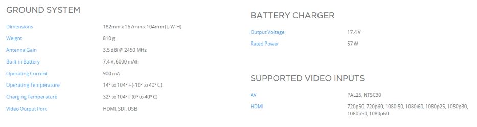
Appendix A - Lightbridge 2 Ground System
https://www.dji.com/lightbridge-2 The controller side of the DJI Lightbridge 2 system. A person can send commands to the air system by having the ground system connect to it and moving the sticks. Moving the sticks dictates directional movement of the drone.
 <br>
<br>
 <br>
<br>
Appendix B - Lightbridge 2 Air System
https://www.dji.com/lightbridge-2 The receiver side of the DJI Lightbridge 2 flight system. In addition to receiving commands from the controller it is also able to transmit back to the controller. The returning signal is for making sure that the controller side of the system gets the required acknowledgement and telemetry information from the drone.
 <br>
<br>
 <br>
<br>
Appendix C - DJI Phantom 4
https://www.dji.com/phantom-4 A lighter more streamlined version of the Matrice. This drone can be paired with the A3/N3 flight controllers. One of the drawbacks of this model was that there was much less room for customizability compared to other options.
 <br>
<br>
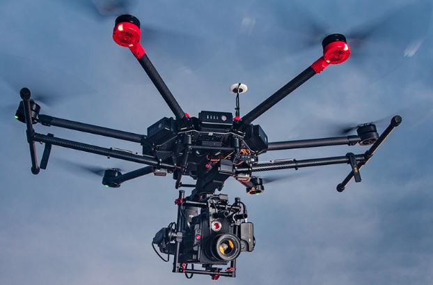
Appendix D - DJI Matrice 600
https://www.dji.com/matrice600 The DJI Matrice 600 is a more customizable and ‘heavyweight’ version of the Phantom 4. Drawbacks of this drone include its high price and that it’s incompatible with non DJI products. One of the benefits of using this drone is that it has the A3 flight controller integrated into its design.
 <br>
<br>
 <br>
<br>
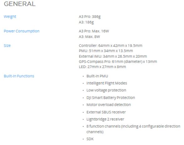
Appendix E - DJI A3
https://www.dji.com/a3 Flight controller for DJI that can output command information.
 <br>
<br>
 <br>
<br>
Appendix F - DJI Assistant 2
https://dl.djicdn.com/downloads/dji_assistant/20180102/DJI+Assistant+2+Release+Notes%EF%BC%881.2.0%EF%BC%89.pdf Above is a link to the release notes for the DJI Assistant 2 simulation software release notes. This software runs on the user’s PC which is connected to the drone via USB cable. When this software is running and the computer is connected to the drone, it displays a simulation of the drone’s movements on the screen of the computer. The DJI Assistant 2 software allows for drone control software/hardware to be tested without having the actual drone flying. For obvious purposes such as the drone causing damage to the surrounding environment and itself, this software is very useful in the beginning stages of drone control development.
Appendix G - STM32F401re Microcontroller
http://www.st.com/en/microcontrollers/stm32f401re.html
 <br>
<br>
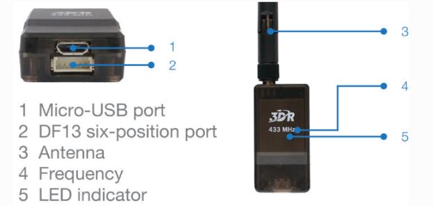
Appendix H - 3DR Radio Wireless Set
http://ardupilot.org/copter/docs/common-sik-telemetry-radio.html This telemetry set model uses MAVLink protocol to send drone commands back and forth between the sets. These radio antennas are able to connect to both a PC running scripts to send/receive commands and 3DR drone flight controllers such as the Pixhawk referenced in the appendix below. Further customization is available for these radios as the firmware is open source. Error correction and frequency hopping/time multiplexing is already built into the protocol making these radios established connection more reliable.
 <br>
<br>
Specs Available in 900MHz or 433MHz Receiver sensitivity to -121 dBm Transmit power up to 20dBm Air data rates up to 250kbps Frequency hopping spread spectrum (FHSS) Adaptive time division multiplexing (TDM) Configurable duty cycle Built-in error correcting code (can correct up to 25% data bit errors)
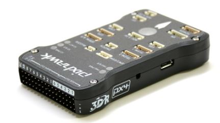
Appendix I - PIXHAWK
https://pixhawk.org/ PIXHAWK is a high-performance autopilot-on-module suitable for fixed wing, multi rotors, helicopters, cars, boats and any other robotic platform that can move. It is targeted towards high-end research, amateur and industry needs and combines the functionality of the PX4FMU + PX4IO. It is compatible with both the 3DR Radio Telemetry Set and the 3DR Solo.
 <br>
<br>
- 168 MHz Cortex M4F CPU (256 KB RAM, 2 MB Flash)
- Sensors: 3D ACC / Gyro / MAG / Baro
Appendix J - 3DR Solo
https://3dr.com/solo-drone/ This drone is what would ideally be used in the ardupilot version of the beyond line of sight relay station design. It is able to interact with the Pixhawk flight controller.
 <br>
<br>
 <br>
<br>
Appendix K - APC220 Telemetry Set
https://www.dfrobot.com/wiki/index.php/APC220_Radio_Data_Module(SKU:TEL0005) A lighter weight and cheaper version of the previous 3DR telemetry radios. Allows the sending of serial information over the channel established by the radios.
 <br>
<br>
- Working frequency: 420 MHz to 450 MHz
- Power: 3.5-5.5V
- Current: <25-35mA
- Working temperature: -20℃~+70℃
- Range: 1200m line of sight (1200 bps)
- Interface: UART/TTL
- Baud rate: 1200-19200 bps
- Baud rate (air): 1200-19200 bps
- Receive Buffer: 256 bytes
- Size: 37mm × 17 mm × 6.6mm
- Weight: 30g
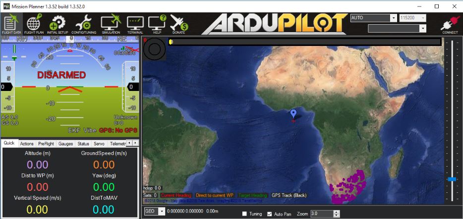
Appendix L - Mission Planner
http://ardupilot.org/planner/docs/mission-planner-overview.html This software is used to control/simulate our Ardupilot drone. As you can see in the top right corner, our radio telemetries never correctly connected.
 <br>
<br>
Appendix M
Relay Module In Depth Setup:
- Acquire required parts for the raspberry pi 3 model b setup including a sd card (minimum 32GB), an sd card reader, a usb cable and a 5V power source for the raspberry pi.
- Download the appropriate software.
- 7 - Zip
- Etcher
- Raspbian Software to be downloaded on the SD Card
- This can be acquired from the download section of the raspberry pi website.
- A program that allows one to SSH into the raspberry pi such as puTTY or an UBUNTU shell.
- Upload the downloaded Raspbian OS onto the SD card using etcher.
- Follow the steps on this stack exchange website which explains how to enable SSH and wifi connection on the SD card while it is in your desktop/laptop.
- Using SSH, run the python receiver side on the raspberry pi.
- Run the a test script using the API sender side.
- The terminal on the PC side of the connection should connect